Zoning In Cisco MDS SAN Switch In Command Line

Zoning In Cisco MDS SAN Switch In Command Line

Zoning is a process of grouping initiator and target ports WWPN which is performed in SAN switch. Once zoning is completed initiator and targets can exchange of FC packets happens between them.

We have already discussed the zoning steps in brocade switch in previous posts. Click here to explore the steps in zoning for brocade.


Zoning In Cisco MDS SAN Switch In Command Line

Steps Of Zoning in Cisco MDS SAN Switch


Below are the overall steps of Zoning that need to perform of zoning. We will discuss more on each steps of zoning while exploring the commands. If the steps seems confused you can check out the post on What Is Zoning which will help you understand why zoning is require.

1. Check Connectivity of HBA Port To Fabric.
2. Create fcAlias Name For HBA Port WWPN and Storage Array Port WWPN.
3. Create a ZONE and add fcalias member in it.
4. Add the newly created zone to active zoneset
5. Commit the zone only applicable if extended zoneset is enabled.
6. Activate the zoneset
7. Copy running config to start up config

Command Of Zoning in CISCO MDS SAN Switch 


First we need to enter into the config mode. All configuration changes happens in configuration mode.

Command to Enter into config mode in Cisco MDS SAN switch


switch# config t


Check the connectivity Of Host In Cisco MDS SAN switch


First we need to check if the host for which we are doing zoning is connected to SAN switch or not. Below Command will check the connectivity of host in Cisco SAN switch. For more information SAN connectivity check out the post of SAN architecture.


switch (config)# show fcns database | grep -i 10:xx:xx:xx:xx:xx:xx:xx

Create fcAlias In Cisco MDS SAN switch


We need to create fcAlias for host WWPN. As WWPN are difficult to remember for better management creating fcalias is good options. Below command creates a fcalias of WWPN with name HostName_hba1in VSAN 3.

switch(config)# fcalias name HostName_hba1 vsan 3
switch(config-fcalias)#
switch(config-fcalias)# member pwwn 10:00:00:23:45:67:89:ab
switch(config-fcalias)#exit
switch(config)# fcalias name Array_Port1 vsan 3
switch(config-fcalias)#
switch(config-fcalias)# member pwwn 50:00:00:53:29:67:89:ab
switch(config-fcalias)# exit
switch(config)#

Create a zone and add fcAlias member In Cisco MDS Switch


After creating fcalias we need to create a zone in VSAN 3. After creating zone we need to add fcalias member into it. Below commands will create a zone with name Zone1 in vsan 3 and add two fcalias member HostName_hba1 and Array_Port1.

switch(config)# zone name Zone1 vsan 3
switch(config-zone)#
switch(config-zone)# member fcalias HostName_hba1
switch(config-zone)# member fcalias Array_Port1
switch(config-zone)# exit
switch(config)#


How To Determine Active Zoneset and Zone and Activate it.


Every VSAN has active zoneset. Every zone has to be a part of it if a zone is not a part of active zoneset then FC exchange or communication between the zone's member will not happen. In below example ZoneSet3 is the active zoneset in vsan 3. We need to add Zone1 in active zoneset ZoneSet3 and then we need to active the zoneset.

Last command will copy the zoning configuration from running config to startup config. This will make sure that even after switch reboot the zoning information is consistent.

switch(config)# show zoneset active vsan 3
zoneset name ZoneSet3 vsan 3 
switch(config)#zoneset name ZoneSet3 vsan 3
switch(config-zoneset)#member Zone1
switch(config-zoneset)#zone commit vsan 3
switch(config)# zoneset activate ZoneSet3 vsan 3.
switch(config)# copy running-config startup-config

If you want zoning steps in more details then explore it from below from an YouTube videos. You can also Subscribe the channel for more upcoming video tutorial on SAN and NAS Technology.

        

Storage Efficiency Feature NetApp Cluster Mode

Storage Efficiency Feature NetApp Cluster Mode 


Storage Efficiency Feature NetApp Cluster Mode

What is Storage Efficiency


Storage efficiency features ensure that there is no wastage of storage capacity and all disk capacity is used in efficient manner without impacting performance. It lowers operation cost.

Storage Administrator has to manage it by enabling and monitoring various storage efficiency feature.

Types Of Storage Efficiency In NetApp Cluster Mode


There are four types Storage efficiency features available in NetApp cluster mode.


  • De-Duplication
  • Thin Provisioning
  • Compression
  • FlexClone

Storage Efficiency Feature De-Duplication


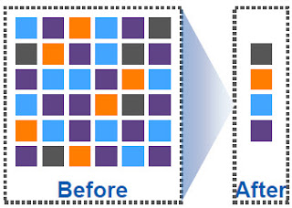
De-duplication reduces the amount of physical storage required for a volume by discarding duplicate blocks and updating the pointer to refer to a single block.

A common example where deduplication is useful is Mail attachment. Same mail attachment is stored by many user which consumes lot of space.

During normal data writing process each data block is assigned with a unique signature. When De-duplication process starts Data Ontap compares these signature and removes all data block which has same signature and keeps only one data block for reference.

Then Data Ontap updates the pointer to the single data blocks. In this way many data blocks is reclaimed and storage efficiency to store same data increases.

Netapp De-Duplication Storage Efficiency


Storage Efficiency Feature Thin-Provisioning


A thin-provisioned volume or LUN is one for which storage is not reserved in advance. Instead, storage is allocated dynamically, as it is needed. It means when user starts putting data in volume actual space is allocated to volume from its containing aggregate.

Free space is released back to the storage system when data in the volume or LUN is deleted.

Thin Provisioning support over provisioning. Example for 5 TB of aggregate you can allocate 7 TB of volumes. As not every user uses all storage that is assigned to them.

Storage Efficiency Feature Compression


Compression reduces the amount of physical storage required for a volume by combining data blocks in compression groups. Then each of these compression groups is stored as a single block.

There are two types of compression:


Inline Compression – Compression happens in memory before the data is written to disk.
Post Compression – Compression happens after the data is written to the disk.

Storage Efficiency Feature FlexClone


FlexClone technology references Snapshot metadata to create writable, point-in-time copies of a volume. Flexclone Copies share data blocks with their parents, hence it does not consumes any extra storage.

You can split the FlexClone to separate it from its parent volume. Once split operation is done the volume will start consumes extra space from aggregate. Watch this video to know more about Flexclone.

Below is a youtube video which explains about storage efficiency in netapp cluster mode. Subscribe To Channel for More Upcoming Videos.


Hardware Architecture NetApp Cluster Mode

Hardware Architecture NetApp Cluster Mode


In this video we will discuss about hardware architecture of NetApp Cluster Mode which includes Components of netapp cluster mode, how Netapp hardware are connected to each other and types of cluster mode and finally we will see how requests flows in netapp cluster mode.

If you are interested for SAN architecture the click here to read more about it.

hardware architecture of netapp cluster mode


Components Of NetApp Cluster Mode Architecture


There are three main components of netapp cluster mode Architecture which are described below.

Controllers Or Node Netapp Cluster Mode


Controller of node is the computing part of NetApp which process all incoming and outgoing request for netapp cluster. Netapp node has slots having IO/Module which has Ethernet, FC, FCoE and SAS Port. Ethernet ports connects to network switches for LAN connectivity. FC port connects to SAN switches which support FC protocol. You can use FCoE for both as Ethernet and FC ports.

Last SAS ports connects the controller to disk shelves. Node also contains main other small hardware such as NVRAM, CPU, PSU and Fans which has different purpose.

Disk Shelves NetApp Cluster Mode


Disk shelves in Netapp Cluster Mode consists of Physical disks. NetApp support various types of disk and has various models as well. Click the link for more details.

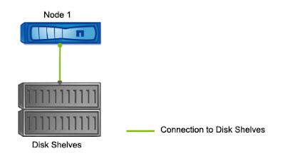
Disk shelves and controller are connected to each other via SAS ports. In a HA Pair the disk shelves are connected to both controller.

Inter Cluster Switches NetApp Cluster Mode


Inter cluster switches or cluster switches are network switches which provides connection between Controllers for data flows. Each node in cluster has minimum of two cluster port which connects to cluster switches.

What Is Cluster Mode NetApp


Cluster Mode NetApp is basically combination of multiple HA Pair Nodes which are interconnected via Inter Cluster Switches for data flow.

Cluster Mode Set Up Can be of three types. First once is Single Node Cluster, second one is Two Node Switchless Cluster and the last type is Two Node Netap Cluster with cluster switches.

In Netapp Cluster Mode the cluster with switches can have maximum of 24 nodes which means 12 HA Pairs.

Single Node Netapp Cluster


In Single node netapp cluster has only one node. Single node cluster does not provide and redundancy and always has risk of outage and data loss.

Single node netapp cluster

Two Node Switch less NetApp Cluster 


Two node switch less cluster has two nodes in HA pair. These nodes are connected to each other directly and not via inter cluster switches. The direct connection between two node for data flow is called as Cluster Interconnect.

Two node switch less netapp cluster

Two Node NetApp Cluster With Cluster Switch


In Two Node NetApp Cluster the nodes are connected to each other via Inter Cluster Switches for Data Flow.


Two node netapp cluster with cluster switches


Four Node NetApp Cluster Mode With Cluster Switch


Four node NetApp Cluster consists of four node means two HA pair. All Nodes are connected to two cluster switches. If you want to add another HA pair to cluster then first perform the physical connection of nodes to both cluster switches.

Four node netapp cluster with cluster switches


How Data Flows In NetApp Cluster Mode


First Read or write request comes to any one of the NetApp node. Data Ontap check if the data resides on local node or remote node.

If Data found in local node request is processed and sent back to client through same path. Now If Data does not present in local node and exists in remote node then request is sent to remote node via cluster network.

In remote node data is processed and the request is sent back to client through the same path.

Hope you gain some knowledge on hardware architecture of netapp cluster mode. For all list of blog on netapp cluster mode click here.
To watch a this blog on Video mode visit our YouTube Channel and Subscribe as well.


Zoning In Cisco MDS SAN Switch In Command Line

Zoning In Cisco MDS SAN Switch In Command Line Zoning is a process of grouping initiator and target ports WWPN which is performed in SAN ...