Hardware Architecture NetApp Cluster Mode
In this video we will discuss about hardware architecture of NetApp Cluster Mode which includes Components of netapp cluster mode, how Netapp hardware are connected to each other and types of cluster mode and finally we will see how requests flows in netapp cluster mode.
If you are interested for SAN architecture the click here to read more about it.
Components Of NetApp Cluster Mode Architecture
Controllers Or Node Netapp Cluster Mode
Controller of node is the computing part of NetApp which process all incoming and outgoing request for netapp cluster. Netapp node has slots having IO/Module which has Ethernet, FC, FCoE and SAS Port. Ethernet ports connects to network switches for LAN connectivity. FC port connects to SAN switches which support FC protocol. You can use FCoE for both as Ethernet and FC ports.
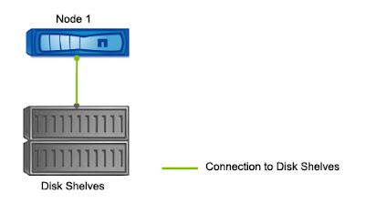
Last SAS ports connects the controller to disk shelves. Node also contains main other small hardware such as NVRAM, CPU, PSU and Fans which has different purpose.
Disk Shelves NetApp Cluster Mode
Disk shelves in Netapp Cluster Mode consists of Physical disks. NetApp support various types of disk and has various models as well. Click the link for more details.
Disk shelves and controller are connected to each other via SAS ports. In a HA Pair the disk shelves are connected to both controller.
Inter Cluster Switches NetApp Cluster Mode
What Is Cluster Mode NetApp
Cluster Mode Set Up Can be of three types. First once is Single Node Cluster, second one is Two Node Switchless Cluster and the last type is Two Node Netap Cluster with cluster switches.
In Netapp Cluster Mode the cluster with switches can have maximum of 24 nodes which means 12 HA Pairs.
Single Node Netapp Cluster
In Single node netapp cluster has only one node. Single node cluster does not provide and redundancy and always has risk of outage and data loss.
Two Node Switch less NetApp Cluster
Two Node NetApp Cluster With Cluster Switch
Four Node NetApp Cluster Mode With Cluster Switch
How Data Flows In NetApp Cluster Mode
If Data found in local node request is processed and sent back to client through same path. Now If Data does not present in local node and exists in remote node then request is sent to remote node via cluster network.
In remote node data is processed and the request is sent back to client through the same path.
Hope you gain some knowledge on hardware architecture of netapp cluster mode. For all list of blog on netapp cluster mode click here.
To watch a this blog on Video mode visit our YouTube Channel and Subscribe as well.


