Port Channel Configuration Cisco MDS SAN Switch

In this blog we will discuss what is port channel in Cisco MDS switch. Along with we will also talk about F Channel, what are the types of port channel, Modes of port channel. Finally we will see the commands for creating a F port channel between a Cisco MDS core switch and NPV switch.

Port Channel Configuration Cisco MDS SAN Switch

What Is Port Channel In Cisco MDS SAN Switch


Port Channel is basically a Cisco SAN Switch Terminology. Port Channel is logical aggregation of Individual FC port or FC interfaces which increase total bandwidth, provides load balancing and link redundancy.

Port channel can connect interface between two different modules in same SAN switch. Port channel can not have interface from different SAN switches. This is more clear in below diagram.

Port Selection In Cisco MDS Port Channel

Above diagram has two switch switch1 and switch2. There are three port channel between the switches PortChannelA, PortChannelB and PortChannelC. In PortChannelA has aggregation of ports from same module in both switches while PortChannelB has ports from different modules.

Now in case of PortChannelC there are three port of from each switch. In switch1 two ports are from same module but third port is from different module. In switch2 all three ports are from same module.
The conclusion here is that you can select various port combination in same switch but ports cannot be selected from different switches.

What are the Types Of Port Channel


Types of port channel is defined based on the type of connectivity between devices. In general there are two types of port channel E port channel and F port channel.

E Port Channel is logical combination of Multiple E ports which Connects two SAN Switches for ISL connectivity. If we enable trunking then the port channel becomes TE port channel and the ISL link becomes EISL.

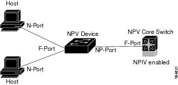
F Port Channel is Logical Combination of Multiple F ports which connects from one Switch (F) to NPV switch (NP) or FI interconnect. If trunking is enabled F port channel becomes TF port channel.

Modes Of Port Channel In Cisco MDS Switch


There are two types Port Channel Mode one is ON and other is ACTIVE. Both modes has different purpose. Below are some basic differences between them.

ON ACTIVE
Default You must explicitly configure this mode.
Need To Disable port while adding or modifying members to port channel When you add or modify a Port Channel automatically recovers.
Not Recommended Recommended
Only Supports E port channel Supports both F and E port channel

How To Configure F Port Channel In Cisco MDS Switch


This section we will discuss how to create a F Port Channel between Cisco MDS switch and NPV switch. Before we start we have to check few things which are very important for port channel configuration.

First thing we need to make sure that Physical connection is present between switches. Some of the configuration of individual ports and port channel must be same. Make sure Configuration like Speed, Mode, Rate mode, Port VSAN, Trunking mode and Allowed VSAN for individual port and port channel are same. If these are different then we may get error while creating port channel

Steps and Commands To Configure F Port Channel


Step 1. Enable F port trunking and channel protocol on the MDS core switch.


Cswitch(config)# feature fport-channel-trunk

Step 2 Enable NPIV on the MDS core switch:


Cswitch(config)# feature npiv

Step 3 Create the PortChannel and Add Ports on the MDS core switch


This command create a port channel with name 1.


Cswitch(config)# interface port-channel 1


This commands ensures the port channel type is F port channel


Cswitch(config-if)# switchport mode F


Below commands sets channel mode active. F port channel only support ACTIVE port channel mode hence it is important to set the channel mode as ACTIVE.

Cswitch(config-if)# channel mode active

Below Command disable the truncking in Port Channel

Cswitch(config-if)# switchport trunk mode off

Below command is use to set the rate mode in port channel

Cswitch(config-if)# switchport rate-mode shared
Cswitch(config-if)# exit

Till now we have completed creating a F port channel in Core Switch whose number is 1. Now in below steps we will Add Interface To the Port Channel 1. Make a note that the configuration for Port Channel 1 and the interfaces must be same.

Step 4. Configure the PortChannel member interfaces on the core switch


Below two commands selects ports fc2/1 , fc2/2 and fc2/3 as port channel members and then disables them
cswitch(config)# interface fc2/1-3
cswitch(config-if)# shut

Below four commands will set port mode as F, disables the trunking, set the speed as 4000 and the rate mode as shared.

cswitch(config-if)# switchport mode F
cswitch(config-if)# switchport trunk mode off
cswitch(config-if)# switchport speed 4000
cswitch(config-if)# switchport rate-mode shared

Below commands is for adding the interfaces to port channel. In this case ports fc2/1 , fc2/2 and fc2/3 added to Port Channel 1. The next command will disable all ports.

cswitch(config-if)# channel-group 1
cswitch(config-if)# no shut

So far we have completed the port channel configuration in Core switch. Now we have to repeat the same steps and commands to configure F Port channel in NPV switch.

Step 5 Create the PortChannel on the NPV switch


eswitch(config)# interface port-channel 1
eswitch(config-if)# switchport mode NP
eswitch(config-if)# switchport rate-mode shared
eswitch(config-if)# exit

Now we have to configure the individual ports and add them To Port Channel 1 in NPV switch.

Step 6 Configure the PortChannel member interfaces on the NPV switch:


eswitch(config)# interface fc2/1-3
eswitch(config-if)# shut
eswitch(config-if)# switchport mode NP
eswitch(config-if)# switchport speed 4000
eswitch(config-if)# switchport rate-mode shared
eswitch(config-if)# switchport trunk mode off
eswitch(config-if)# channel-group 1
eswitch(config-if)# no shut

Final step is to disable and enable all interfaces from both Core switch and  NPV switch.

Step 7 Set the administrative state of all the PortChannel member interfaces in both NPIV core switch and the NPV switch to ON:


Disable and enables interfaces in Core switch.

cswitch(config)# interface fc1/1-3
cswitch(config-if)# shut
cswitch(config-if)# no shut

Disable and enables interfaces in NPV Switch

eswitch(config)# interface fc2/1-3
eswitch(config-if)# shut
eswitch(config-if)# no shut

This completes the port channel configuration between Cisco MDS SAN switch and a NPV switch. Hope you have like this. Watch below YouTube for more details. Feel free comment on this topic and Subscribe For more such videos


Volume Rehost In Cluster Mode NetApp

How To Re-host Volume From One SVM To Another SVM Cluster Mode NetApp


In this Blog we will see what is Volume Rehost and how we can move or rehost volume from one vserver to another vserver in NetApp Cluster Mode. In later section we will also move a CIFS volume from one SVM to another SVM  via command line.

Volume rehost in netapp cluster mode


What is Volume Rehost in NetApp Cluster Mode


Volume rehost enables you to reassign NAS or SAN volumes from one storage virtual machine (SVM, formerly known as Vserver) to another SVM without requiring a SnapMirror copy.

Volume rehost is a disruptive operation for data access. Hence you should get a downtime from share owner and then plan it within that downtime window.

Volume Eligible For Rehost In NetApp Cluster Mode


The volume rehost procedures depend upon the protocol type and the volume type. Based on these the steps to perform volume rehost differs. Below is the brief summary for volume rehost for different scenario.

Rehosting CIFS volumes


You can rehost volumes that has CIFS shares. After rehosting the CIFS volume you must mount the volume and create a CIFS share in destination SVM. Volume rehost moves NTFS ACL so no need to worry about permission mismatch. To know how to create cifs share click the Link

Rehosting NFS volumes


You can rehost volumes that serve data over NFS protocol. After rehosting the NFS volumes, you must mount the volume create export policy and permission rules in destination SVM. Click the Link for more details on creating export-policy and rules.

Rehosting SAN volumes


You can rehost volumes that have mapped LUNs. After re-creating the initiator group (igroup) in the destination SVM, volume rehost can automatically remap the volume on the same SVM.

Rehosting volumes in a SnapMirror relationship


You can rehost volumes in a SnapMirror relationship. Before rehosting you should delete the snap-mirror relationship. After volume rehost you must create peer relationship between source and destiantion SVM. You should also create new snap-mirror relationship and schedule it for Sync.


Pre Check For Volume Rehost From In NetApp Cluster Mode


Volume must be online. Offline volume cannot be rehosted Volume management operations, such as volume move or LUN move, must not be running. Data access to the volume must be stopped. Destination SVM Configuration must match with Source SVM.

Post Steps Of Volume Rehost In NetApp Cluster Mode


After the rehost operation volume will lost Some configuration such as Antivirus policies, Volume efficiency policy, QOS, Snapshot policies , Quota rules, export policy and rules, User and group IDs. If any of the above feature was there for rehosting volume them you must create these in destination SVM as well.

You also need to mount the volume and the create new share. Good thing is that NTFS permission will be the same as it was in source SVM. Last thing is that you have to use destination SVM IP to access the shares.

Steps And Commands For Volume Rehost In NetApp Cluster Mode

  1. Record information about the CIFS shares to avoid losing information on CIFS shares in case volume rehost operation fails.
  2. Unmount the volume In Source SVM:volume unmount -vserver vs1 -volume vol1
  3. Switch to the advanced privilege level:set -privilege advanced
  4. Rehost the volume on the destination SVM:volume rehost -vserver vs1 -volume vol1 -destination-vserver vs2
  5. Mount the volume under the appropriate junction path in the destination SVM:volume mount -vserver vs1 -volume vol1 -junction-path /vol1
  6. Create CIFS shares for the rehosted volume:vserver cifs share create -share-name share1 -vserver vs1 -path /vol1
  7. Point the DNS Host entry to IP of New SVM.

Checkout the YouTube Video on Volume Rehost In Cluster Mode NetApp. This videos has live demo for volume rehost. Subscribe to Channel for more such videos.


Details Explanation Of SAN Storage Architecture

Details Explanation Of SAN Storage Architecture


This blog explains What is SAN storage how SAN storage works. What are the SAN Storage components and how they connects to each other.

Details Explanation Of SAN Storage Architecture


What is SAN Storage ?


SAN storage stands for Storage Area Network. A SAN is a specialized high‐speed network of storage devices and SAN switches connected to computer systems called as Host or Server via Fiber optic cables. Host uses the storage from storage arrays as if its local to Host. As the data communication happens via fiber optics the data speed is high in comparison to NAS storage.

Components Of SAN Storage 


SAN Components can be divided into 3 layer. Host, Fabric and Storage Layer. These three layers connects to each other and form an Storage Area Network or SAN network. Each layer has its own functions. We will discuss about their function in coming section.

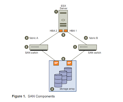
Below is a very simple architecture diagram of SAN storage which has all of Storage Area Network.

                           basic architecture of SAN storage

Host Layer Of SAN Storage


Host layer of SAN Storage has servers or host. Hosts are basically a hardware having its own resources like CPU, Memory, Disk storage and an Operating system running on it. Along with these it has also dual HBA card which connects to the Fabric Layer of SAN Network.

What is Fabric In SAN Storage


Fabric layer or a Fabric of SAN storage consist of one or more SAN switch. SAN Switch provides a connections points in SAN architecture. All Host connects to SAN switch and Storage Array also connects to same SAN switch. Thus it act as mediator between Host and Storage.

Typical SAN network has two fabric for high redundancy. In case if one Fabric goes down then other fabric takes care of the data flows in storage area network.

Storage Layer in Storage Area Network


In storage layer of Storage Area Network storage arrays are present where data resides in physical disks. Storage Array consist of physical disk. These disks are grouped logically using special technology called RAID for data protection. These RAID helps in data recovery whenever a disk failure occurs. There various types of RAID type. Depending on requirement specific RAID type is selected for creating raid group. Common RAID type are RAID 5 and RAID 6.

Most of storage arrays has Dual storage processors (SPs) which are the front end of the storage array. These SP has front end IO module which has FC ports. These FC ports connects to SAN switch via FC cables.

Below is an architecture diagram of typical SAN storage which has all components of Storage Area Network with redundant setup.

Image of Storage Area Network SAN Storage


How SAN Storage Works 


When a host from a host layer wants to access a storage device on the SAN, it sends out a block‐based access request for the storage device. SCSI commands are encapsulated into FC packets. Then the Host HBA transmits the FC request to the Storage layer via Fabric.

From Fabric layer SAN Switch then sends this request to Storage Array. In Storage Array SP receives the request, process it and then sends an acknowledgement back to the host through same path.

For more detail explanation on this topic please watch this YouTube Video. For more such videos on SAN and NAS technology Subscribe to the channel.


What Is And How NPV Works SAN Switch

What Is And How NPV Works SAN Switch

In this blog we will discuss what is NPV and how NPV works in SAN switch. NPV sounds similar to NPIV but they are different in terms of their use. Click the link to check what is NPIV and how NPIV works in SAN switch. For all tutorial under SAN switch click here.

what is npv and how npv works in san switch

What Is NPV In SAN Switch


What is NPV In SAN Switch ? NPV stands for N_Port Virtualization. This is SAN Switch level features. NPV enabled switch act as a proxy switch and bypass all FC services request to its up-link switch. NPV is a Cisco Specific term other vendor calls it as different name. In terms of Brocade its called as Access Gateway Switch.


How NPV Works In SAN Switch


In order to understand how NPV works we should understand what happens when a new switch connects to fabric. In usual case when a SAN switch is connected to a fabric its gets Domain ID and participate in Fabric Services like assigning FCID to initiator.

Now in case of NPV if the SAN switch is NPV enabled then it will not have any Domain ID and does not participate any FC services. Whatever Device connected to NPV enabled switch such as host , switch or UCS or any device gets FC services from its up-link switch.

what is and how npv works in san switch


Use Of NPV SAN Switch Network


There are various ways to use NPV in SAN switch. Below are some examples where we can use NPV. One of the rare use of NPV where fabric requires more then 239 switches or there is a limitation of Domain ID. For each switch in a fabric it requires a domain ID. Now as the fabric grows number of SAN switch also grows and as a result Domain ID also grows. If the number of switches reaches to 239 domain id also reaches to 239. In such scenario if more switches requires then NPV is a solution to add more switches to fabric.

Another practical use of NPV is multi vendor SAN switches in same fabric. If you have a SAN fabric with switches of multiple vendor then NPV is necessary. For example you can connect a Cisco Core switch with brocade SAN switch. Note both switches must be interoperability mode.

You can also use NPV for migrating SAN switches from one vendor to another. We can use NPV as pre deployment stage for SAN switch migration from one vendor switch to another. For more details you can visit the below link.

Below is an YouTube videos which have details explanation of NPV features and its uses. Subscribe the channel for more such videos on SAN switch training.


What Is And How NPIV Works In SAN Switch

What is NPIV In SAN Switch

NPIV is SAN switch port level virtualization feature. NPIV stands for N-Port ID Virtualization. NPIV allows multiple initiator to logged in to same single physical target port. NPIV is mostly used SAN network where ESX Host, Blade Server and UCS deployment are present.

What Is And How NPIV Works Basics Of SAN Switch Part 5

How NPIV Works In SAN Switch

In order to understand how NPIV works in SAN switch first lets understand how a SAN connectivity works without NPIV. In usual case one initiator or host is connected to single port of SAN switch.
During FLOGI process the switch assign a FCID to initiator and the initiator is logged in to switch port.

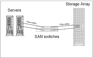
Below is one diagram which has simple connectivity of two server to SAN switch. where two server use two ports of SAN switch to logged in.

Basic Connection Between Server and SAN Switch


Now in case of NPIV multiple initiator tries to login to same single physical port of SAN switch. If SAN switch port is NPIV enabled then switch port accepts request from each initiator and assign a FCID to each initiator. Once all initiator receives a FCID all of them are logged to to same physical port.

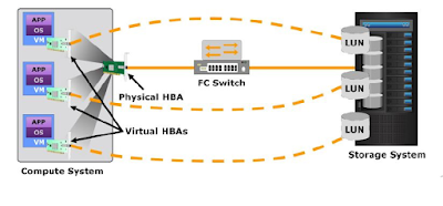
Below diagram explains the connectivity and uses of NPIV in SAN switch network. Here compute system which is similar to blade server of ESX host which has single physical HBA which connects to single SAN switch port. In back-end the compute system has multiple nodes which shares same common physical HBA. Each node of compute system has a virtual HBA having virtual WWPN.

During FLOGI Process each virtual WWPN send request to same SAN switch port and if the SAN switch port is NPIV enabled it accepts all request and assign FCID to each node or initiator. This way multiple initiator logged in same SAN switch port.

What Is And How NPIV Works In SAN Switch

Where We Use NPIV In SAN switch

There are various uses of NPIV in SAN network but below are most common use of NPIV.
If your environment has ESX, UCS, or Blade Server Deployment then definitely your SAN switch ports are NPIV enabled.

Second common use of NPIV is that it allows masking of LUN to individuals VMs. It means if you have multiple VMs in ESX host then you can do zoning between the VMs WWPN and Storage array. Then you can share individual LUNs to particular VM.

Third common use is that it reduce messy cable connectivity of SAN network. If you have large number of server then lot of cable connection is require between server and switch which makes difficult for Data Center admin to perform physical maintenance activity. As NPIV reduce the number of connection between server and switch physical management of Data center make simpler.
Below is one of the videos which explains the purpose of NPIV and how it works. Subscribe to YouTube Channel for such videos.      


What is FLOGI PLOGI and PRLI In SAN Switch

What is FLOGI PLOGI and PRLI In SAN Switch

What is FLOGI PLOGI and PRLI In SAN Switch read this blog and you will get the answer. This blog has detail explanation of three device login process on SAN switch. Basically there are three device login process FLOGI, PLOGI and PRLI.

What is FLOGI PLOGI and PRLI In SAN Switch

What is Device Login In SAN Switch ?

Device Login is a series of process which happens when a new node or devices is connected to a Fabric. Once Device Login Process Completes then a device can communicate with other devices in same fabric. Its Involves three steps FLOGI PLOGI and PRLI.

Components of Device Login In SAN Switch

Host – These are the server which are connected to Switch.
Array – These are the storage Array connected to Switch
SAN Switch – A SAN switch having FC Ports

Not only above three devices any other device which connects to SAN switch with FC protocol has to go through device login process..

What is FLOGI Process in SAN switch network

FLOGI Process happens when a new device is connected to switch or fabric for the first time. Once the device is power the device sends it first frame to the switch where it is connected. The first frame contains some information like WWPN and buffer to buffer credits (B2B credits).

The switch reads these information and then assign a 24 bit Unique ID address to device. This unique ID called as FCID. Switch uses this FCID to identify the end device connected to it in SAN network. Then the end device also confirms to the switch that it received FCID.

What is PLOGI SAN Switch Network.

Port initialization in PLOGI Process in SAN Switch

PLOGI Process has two port initialization and registration in Name Server. During port initialization information like port type and port speed are exchanged between end device or host and SAN switch. SAN switch use these information and negotiate with host. During negotiation SAN switch will come to know whether the end device is a server or a storage by referencing the port type.

What is Name Server In SAN Switch Network

During Name Server registration of PLOGI process the device register its information in Name server. This provides information to device about all other device which are registered in name server that it can communicate to.

Each fabric is SAN switch network maintains a name server. These name server contains the information of every devices connected to the SAN Fabric. Two device in SAN switch network can communicate only if both of them are Name server.

What is PRLI Process Login In SAN Switch

PRLI also stands for process Login. During this process actual communication happens between device connected to switch which are present in Name Server. In simple terms we can say that a during PRLI N_port communicates with another N_Port. In broad term a host communicates with storage array.

During PRLI process a host sends a PRLI request to storage array. If proper zoning and LUN masking is exists then storage array accept the PRLI request and start a communication between them.

Device Login Process SAN Switch With Diagram

Below is a diagram which explains step by step process of Device login in SAN switch network. Subscribe the blog for more such article.

Device Login Process SAN Switch With Diagram

Video Tutorial On Device Login Process SAN Switch

Watch the below videos tutorial from YouTube explaining the device login process in SAN switch. Subscribe the channel for more such videos.


Zoning In Brocade SAN Switch

Zoning In Brocade SAN Switch

Zoning In Brocade SAN Switch. We will discuss about zoning in brocade switch in details.Zoning is necessary to provide a secure path for SAN Host to access Storage Array. We will discuss how we can do zoning in brocade switch via command line.

Zoning in Brocade SAN Switch


Important Terms Brocade SAN Switch Zoning

Lets first some important terms on Brocade SAN switch zoning which is useful to understand the process
of zoning in brocade SAN switch.

What is WWPN in Brocade SAN Switch Zoning

WWPN stands for World Wide Port Name. Each port in SAN network has a unique WWPN. In SAN network port are identified by its WWPN. A WWPN is 64 bit address. Below is an example of WWPN
Ex : 10:xx:xx:xx:xx:xx:xx:xx

What is Alias Name In Brocade SAN Switch

Alias Name In Brocade SAN Switch are Human readable name of WWPN. As WWPN are 64 bit address and difficult to remember. SAN Switch admin provide a name for WWPN for easy reference.

What is Zone Brocade SAN Switch

Zone in Brocade SAN Switch are nothing but Group of alias member. These member are alias of Host WWPN and Storage Array WWPN.

Active Zone Configuration SAN Switch

Active Zone Configuration SAN Switch consists of Group of Zones in Active State. In a fabric only one Zone config can be in active state and the zones present inside it are effective zones.

What we need before Zoning Brocade SAN switch

Below are some of the information we need before we start ding zoning in Brocade switch

SSH Or GUI connectivity to Brocade SAN switch
Server Name For Zoning
Two WWPN  of Server HBA Port- Connected to each Fabric
Ex : Host1: 10:xx:xx:xx:xx:xx:xx:xx
WWPN of Front End Storage Array Port Connected to Fabric
Ex: Array_Port1 : 50:xx:xx:xx:xx:xx:xx:xx:xx

Steps Of Zoning in Brocade SAN Switch

Once we have the above information. Below are the steps we need to perform. These are overall steps of zoning in brocade switch In next section we will see the CLI commands for zoning.

1.Check Connectivity of HBA Port To Fabric.
2.Create Alias Name For HBA Port WWPN and Storage Array Port WWPN.
3.Create a ZONE and add alias member in it.
4.Add the zone to active configuration zone
5.Save the active configuration zone
6.Enable active configuration zone

In some SAN network some additional feature are enabled for more security. Based on that the zoning may include more steps

CLI Command for Zoning in Brocade SAN Switch

CLI Command for Zoning in Brocade SAN Switch are executed by login to SSH or via Putty session on Switch. Below are the CLI commands of Brocade SAN switch zoning.

1.Check Connectivity of HBA Port To Fabric.
nodefind 10:xx:xx:xx:xx:xx:xx:xx
2.Create Alias Name For HBA Port WWPN and Storage Array Port WWPN.
alicreate “host1_hba1”,”10:xx:xx:xx:xx:xx:xx:xx”
3.Create a ZONE and add alias member in it.
zonecreate “zone1”, “host1_hba1; Array_Port1 ”
4.Add the zone to active configuration zone
First we need to find out which zone config in in active state using command.
cfgactvshow | more
cfgadd "activecfg1",“zone1”
5.Save the active configuration zone
cfgsave
6.Enable active configuration zone
cfgenable "activecfg1“

Today’s Question on Zoning In Brocade SAN Switch

Now a tricky question for you guys. Do research and let me know your answer in comment section.

What is the purpose of cfgsave command ?
What will happen if cfgsave command is not executed ?

Below is video on SAN switch zoning. Watch it Like it, Share It and subscribe the channel for more such videos.


What Is Zoning - SAN Switch Tutorial Part 2


What Is Zoning - SAN Switch Tutorial Part 2

This videos explains what is Zoning why we need zoning and what are the types zoning and difference between them In SAN Switch.

What Is Zoning - SAN Switch Tutorial Part 2

What Is Zoning - SAN Switch Tutorial Part 2


What is WWNN and WWPN ?

WWNN stands for World Wide Node Name and it a unique identification for each device or nodes connected in SAN network.

WWPN  stands for World Wide Port Name. If any devices like or SAN storage array in SAN network has FC ports on it. Then it will have a unique identification which is WWPN.

Each device in a fiber channel Network will have a unique WWNN for each vendor and the Ports under it will have WWPN.

What Is fcalias, device-alias and alias?

fcalias and device-alias are CISCO SAN switch terminology. The WWPN are hard to remember hence an alias name is created for WWPN for easy reference. We can use fcalias within a single VSAN but devices alias are span across VSAN.

Similarly alias is Brocade SAN switch terminology. We can use alias for easy reference of WWPN. It is a 64bit address which is unique to each vendor.

Why We Need Zoning ?


There are various reason for zoning. The most important is security. In a SAN network many devices are connected to SAN switch. In order to make sure that the traffic flows between the intended device we create zoning. Zoning provides a secure path between an initiator and a storage array.

What Is Zoning ?


Zoning is binding or grouping of initiator port and target ports which ensures flow of traffic between a particular initiator and target. Zoning involves 3 to 4 steps which is performed in SAN Switch.

What are the types of Zoning ?
In simple terms there are two types of Zoning Hard Zoning and Soft Zoning.In most environment soft zoning is used. Hard zoning is very rare but as its more secure then soft zoning it is used for highly secure SAN network.


Difference between Hard Zoning and Soft Zoning ?


In Hard Zoning Domain ID and Port number of Switch are used to do zoning but in soft zoning WWPN of the Port or fcalies are used for zoning. Hard Zoning is highly secure then soft zoning.

In case of Hard Zoning If any physical changes in SAN network like cable swap between SAN switches happens then rezoning needs to be done. In case of Soft Zoning any physical changes like cable swap between SAN switches does not impact anything.

Check out the below videos for more details and subscribe to You Tube Channel for more such videos.


Basics Of SAN Switch - SAN Switch Tutorial Part 1

Basics Of SAN Switch - SAN Switch Tutorial Part 1

This videos explains a very basic concept of SAN switch. In later video we will discuss more on SAN switch.
Basics Of SAN Switch - SAN Switch Tutorial Part 1


What Is SAN Switch ?

SAN Switch is a hardware which have FC Ports. Host and Storage device are connected to it
It establish a communication link between host and storage device.

A Group of SAN switch is called as Fabric. Every SAN network has two fabric for redundancy. Popular Vendor Are Brocade and

Types Of Ports In SAN Network


F_Port: This is called as fabric port. This port is configured in SAN switch. This port connects to N_Port via fiber cable.

N_Port: This is called as node port which represents a target or host port. N_Port are connected to F port in SAN Network.

E_Port: This is called an expansion port. A port is which is designated an E_Port connects to the E_Port of another switch, to enlarge the switch fabric. This link is also called as Inter Switch Link (ISL).

G_Port: This is a generic port that can operate as either an E_Port or an F_Port.

Simple Architecture of SAN Network.


Below diagram show a simple connectivity of SAN switch in a Storage Area Network. This picture also shows the types of port in it.

Simple Diagram Of SAN Switch Network

Complex Architecture of SAN Network.


Below diagram show a complex connectivity and architecture of Storage Area Network.

Complex Architecture of SAN Network.


Checkout out the below YouTube Video for explanation.


How To Recover Deleted Volume In Netapp Cluster Mode


How To Recover Deleted Volume In Netapp


In this video we will see how we can recover a deleted volume in NetApp cluster mode. This features is available in data ontap 8.3 and in later version. If you have deleted a volume and this feature is enabled then you can recover that volume within certain period of time.

How To Recover Deleted Volume In Netapp Cluster Mode

To see if the feature is enable or not execute the below command

vserver show -fields volume-delete-retention-hours -vserver vs1

The value under volume-delete-retention-hours indicates the retention period of the deleted volume in a vserver. If its none then the feature is not enabled. In order the enable the feature execute below command.

vserver modify -volume-delete-retention-hours 8 -vserver vs1

Above command will set the retention period of 8 hours of all volume under SVM vs1. Below command will show what are the volume which are in recovery queue or in other sense which are in pending delete state.

volume recovery-queue show -vserver vs1

Below command will recover the volume from recovery queue

volume recovery-queue recover -vserver vs1 -volume vv4_1033

After using the recover command, the following steps must still be performed to access the data.

  1. Rename the volume running the volume rename command.
  2. Set up a junction, if required, running the volume mount command.
  3. Create mappings for LUNs in the volume, if required, run the lun map command.
  4. Associate a snapshot policy, an export policy with the volume, if required, with the volume modify command.
  5. Add new quota policy rules for the volume, if required, with the quota policy rule command.
  6. Add a QOS policy for the volume, if required, run the volume modify command.

Video Tutorial For NetApp Cluster Mode


How To Send Email Using SMTPLIB Python Scripting

How To Send Email Using SMTPLIB Python Scripting

In this script we will see how we can send email using smtplib in python scripting. This script use gmail smtp server to send email hence we have used smtp server of gmail. You need to use your environment's smtp server to run this script.

Below is the entire script which we have written so far. Watch the video for full explanation and subscribe to the channel for more such video.

How To Send Email Using SMTPLIB Python Scripting

import paramiko,smtplib
from email.mime.multipart import MIMEMultipart
from email.mime.text import MIMEText
p = paramiko.SSHClient()
cred = open("cred.csv","r")
for i in cred.readlines():
    try:
        line=i.strip()
        ls =line.split(",")
        print(ls)
        p.set_missing_host_key_policy(paramiko.AutoAddPolicy())
        p.connect("%s"%ls[0],port =22, username = "%s"%ls[1], password="%s"%ls[2])
        stdin, stdout, stderr = p.exec_command("uname -a")
        opt = stdout.readlines()
        opt ="".join(opt)
        print(opt)
        temp=open("%s.txt"%ls[0],"w")
        temp.write(opt)
        temp.close()
        msg= MIMEMultipart('alternative')
        msg['Subject'] = 'Test Mail'
        From = "fromemailaddress@gmail.com"
        To = "toemailaddress@yahoo.co.in"
        Cc = "ccemailaddress@yahoo.co.in"
        text = "Info Collector"
        data = open("%s.txt"%ls[0],"r").read()
        part1 = MIMEText(text, 'plain')
        part2 = MIMEText(data, 'plain')
        msg.attach(part1)
        msg.attach(part2)
        s=smtplib.SMTP('smtp.gmail.com', 587)
        s.ehlo()
        s.starttls()
        gmail_cred = open("gmail_cred.txt","r").read().split(",")
        s.login(gmail_cred[0],gmail_cred[1])
        s.sendmail(From, To ,msg.as_string())
        s.quit()
    except Exception as error:
       print(error)
cred.close()


How Convert Python File To Binary File

How Convert Python File To Binary File


In this script we will see how we can convert a python file to binary file or we can say .py to .exe file. Binary file can be executed in any system without installing the actual scripting language or any module. We will use a python module called pyinstaller to convert a .py file to .exe file.
One thing to note that you have to run the binary file in 64 bit operating system only if you have used a 64 bit operating system to convert .py file to .exe file.


How Convert Python File To Binary File

How Convert Python File To Binary File


First you have to installed the module by executing below command in command prompt.

pip install pyinstaller

Then go to the directory where the .py file is located and the execute the below command to convert python file to binary file.

pyinstaller info_collector.py --onefile

Above command will bundled all dependencies and create a .exe file. The location of the .exe file will be displayed at bottom.

Watch the below video for details explanation. Also Subscribe to channel for more such video


Error Handling In Python Try And Except

Error Handling In Python Try And Except 


In this script we will see how we can implement error handling in python scripting by using try and except method. Sometime is the there is an error in script or in the remote device where you are trying to connect then the script will break and stop working. Error handling using try and except method deals with these kind of situation.

Error Handling In Python Try And Except

Below is the script which we have used error handling. Watch the video for full explanation and subscribe to the channel for more such video.

import paramiko
p = paramiko.SSHClient()
cred = open("cred.csv","r")
for i in cred.readlines():
    try:
        line=i.strip()
        ls =line.split(",")
        p.set_missing_host_key_policy(paramiko.AutoAddPolicy())
        p.connect("%s"%ls[0],port =22, username = "%s"%ls[1], password="%s"%ls[2])
        stdin, stdout, stderr = p.exec_command("uname -a")
        opt = stdout.readlines()
        opt ="".join(opt)
        temp=open("%s.txt"%ls[0],"w")
        temp.write(opt)
        temp.close()
    except Exception as error:
        print(error)
cred.close()


Login To Multiple Server And Run Unix Command Python Script

Login To Multiple Server And Run Unix Command Python Script


In this script we will write python code which will login to multiple Unix server and execute an command. After that what ever output that command will give the script will save it in a text file.


Login To Multiple Server And Run Unix Command Python Script


Overview of Python Script. For live demo watch the video here.

1. Read Credential from CSV file
2. Login to multiple device one by one
3. Execute command
4. Save the output in txt file

Below is the script written python which will login to multiple device and execute command.
Below line will import a module called paramiko which is used for ssh connectivity to UNIX server.

import paramiko

Below line will initiate and object for ssh connectivity.

p = paramiko.SSHClient()

Below line will open a the credential file in read mode where we have credential for the devices.

cred = open("cred.csv","r")

Now below is the for loop which will iterate over each line of the file and get the credential, login to the device and execute a command. Then the ouput of the command for each device will be saved in a text file.

for i in cred.readlines():
    line=i.strip()
    ls =line.split(",")
    print(ls)
    p.set_missing_host_key_policy(paramiko.AutoAddPolicy())
    p.connect("%s"%ls[0],port =22, username = "%s"%ls[1], password="%s"%ls[2])
    stdin, stdout, stderr = p.exec_command("uname -a")
    opt = stdout.readlines()
    opt ="".join(opt)
    print(opt)
    temp=open("%s.txt"%ls[0],"w")
    temp.write(opt)
    temp.close()
cred.close()
           
For More details watch the video and Subscribe and stay tuned for more such videos.


Python Scripting For Storage Admin Part 6 Login Through SSH Execute Command

Python Scripting For Storage Admin Part 6 Login Through SSH Execute Command

Python Scripting For Storage Admin Part 6 Login Through SSH Execute Command


In this video I have explained how we can login to a device using ssh protocol, execute a command and then print the output on the screen by using python script. We will use a module called paramiko to achieve this. Paramiko module needs to be installed before.

Open a command prompt and then execute below command. This will download the module and install it in windows OS. Please note your internet connection should be active.

pip install paramiko

First line will import the module paramiko. You can import any module like this.

import paramiko

Second line will create an object called "p" which will create an SSH session.

p = paramiko.SSHClient()

Below line will add key to SSH session.

p.set_missing_host_key_policy(paramiko.AutoAddPolicy())

In below line we have mention the IP address of the system then port number for ssh protocol. Third and fourth parameter we have mentioned username and password.

p.connect("192.168.15.173",port =22, username = "atish", password="password")

Below is the code where we need to specify the command that we need to execute. If the command is correct and successfully executed then the output will be stored in stdout if any error comes while executing command then it will stored under stderr.

stdin, stdout, stderr = p.exec_command("uname -a")

Below line will convert output which is stored in variable stdout into a list.

opt = stderr.readlines()
Below line will join the above list and convert it into areadable format.

opt ="".join(opt)

Finally below line will print the output.

print(opt)

Subscribe to You Channel and stay tuned for more tutorial video in this series.


Python Scripting For Storage Admin Part 5 - If Else For Loop

Python Scripting For Storage Admin Part 5 - If Else For Loop

In this blog I have explained how we can use if else and for loop in python scripting. These two concept in python scripting is very important because once you know how to implement these in scripting you can convert any task into scripting and automate it.

Python Scripting For Storage Admin Part 5 - If Else For Loop

Below three line we have created two list and and one variable. We will use these as example while using for loop and if else.

ls = ["a","b","c","d"]
ls1 = [1,2,3,4]
line = "i am a list"

In below line we have created a list from the variable "line" using split function. A space character is used within double quotes to create the list.

conv_list = line.split(" ")
print(conv_list)

Below is the output of above print function.

['i', 'am', 'a', 'list']

Now in below line we will use for loop to print all element of the list "conv_list". For loop will iterate over each element of the list and assign the value of the element to a temporary variable "i" and in next line it will print it.

for i in conv_list:
    print(i)

Output of above for loop is as below
i
am
a
list

Below is an example of if and else statement. If the specified condition under "if" statement is true then the block under "if" will get executed other wise the block under "else" will get executed.

if "c" in ls:
    print(ls)
else:
    print("Not found")

Output of above if else code is as below.

['a', 'b', 'c', 'd']

Watch below video for live demo of this tutorial. Dont forget to share and subscribe to the YouTube Channel for more videos on this series.


Python Scripting How To Open Read & Write In File

Python Scripting For Storage Admin - How To Read & Write In File. 

Python Scripting How To Open Read & Write In File

In this videos we will see how we can open file using python script then we will write some content in the file and then save it using python script. This is also called as file handling in python script.

Below is the code which is explained in above video.

Below line will open a file for writing purpose. You can use "r" for read and "a" for append.

s=open("file.txt","w")

This line will write some content in the file. \n is the newline character which writes data in a new line.

s.write("this is a file2\n")

Below line will save the data and close the file. If you miss below line then data will not get saved.

s.close()

This line will read the entire content of file and store it in a variable read_file.

read_file=open("file.txt","r").read()

Below line will print the content which is stored in variable read_file.

print(read_file)      

For more details and live demo please refer to the below video. Subscribe to youtube channel as well and stay tuned for more videos in this video series.


Python Scripting For Storage Admin - Why Python Scripting

Python Scripting For Storage Admin 

Why system admin Should Learn Python Scripting. In this video i have explained few reason to start learning scripting. You can learn any scripting language but choosing python will will give you many advantage as below.

Python Scripting for Storage Admin


1.What is scripting ?

It is a bunch of code written in any programming language which perform certain task in specific sequence.

2.Why Storage Admin Learn Scripting

To make your life easy. If you have lot of server or storage devices which support ssh and regularly login to those device to check health status and it killing your time then learn scripting and automate it. Also if you want to start career in DevOps then you must a scripting language.

3.Why Python

Its a very easy language and platform independent. Its a very powerful language which is widely being used in many popular website.

4.Popular Websites Which Uses Python

nasa.gov
Google Search Engine
InstaGram
Quora

5.What Would be In this Series?

First Couple of video we will discuss about basic in python then we will start write a code which will login to the system remotely and execute some command to get some output.


Zoning In Cisco MDS SAN Switch In Command Line

Zoning In Cisco MDS SAN Switch In Command Line Zoning is a process of grouping initiator and target ports WWPN which is performed in SAN ...